Fibre optic sensors detect intrusion at the fence line.
This technology provides a new dimension in detecting and locating fence line and perimeter intrusions. A laser beam is transmitted along the fence mounted sensor cable and the returned signal is automatically monitored and analyzed by the sensing controller for disturbances on the fence. The returned signed is intelligently processed to minimize nuisance alarms, while still detecting and reacting to a hostile event.
It employs 3 Single mode fibres within the sensor cable attached to the fence fabric as the sensing element. This sensing cable continuously monitors in real-time, any physical disturbances or activity on the fence. It also locates where the disturbance is along perimeter fences, quickly, reliably and accurately. This unique feature allows end users to pinpoint an intrusion on long perimeter sites, such as airports and military bases.
While the technology is sophisticated, its application in a system context is very simple. With some manufacturers the basic system operates over long spans, of 80km of perimeter fencing with a sensing controller and start sensor at one end, and a passive termination device at the remote end. The only system component between these two ends is the fibre optic sensing cable itself. There is no electronics, power or maintenance required in the field. Multiple systems can be networked together, to monitor and protect hundreds, if not thousands of kilometres of fence line.
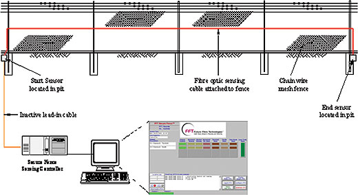
Fig 1: Typical Layout
How it Works
This is effectively a fibre optic ‘microphone’, combining the characteristics of a piezo-electric transducer and strain gauge sensor, designed to detect disturbances generated by intrusions and attempted intrusions on a fence, while discriminating between normal ambient conditions.
The system is sensitive to minute movements of the cable and the fence fabric the cable is attached to. Through the use of intelligent signal processing, these movements can be isolated from other environmental signals for clear identification, with minimal false alarm and nuisance rates.
The system comprises an optical fibre cable attached to the fence fabric and a sensing controller containing the opto-electronics, data acquisition hardware and signal processing software, installed at one end of the fence line (section) to be monitored. Refer Fig 1.
The system can operate in a stand-alone mode and a number of these systems can be integrated into one central monitoring unit for ease of operation.
The system uses single mode optical fibres as its sensor, detecting movement, vibration and sound acting on the cable and the fence it is attached to.
Fig 2: Interferometry
The sensor is based on interferometry where two of the fibres within the sensing cable form the arms of an interferometer. Using a coherent laser, CW light is propagated through the arms of the sensor. When there is an external interference on the sensing fibres (motion, sound or vibrations) an interference pattern will be generated. The sensing controller will detect this change and the software will interpret the effect as either an intrusion event, or reject it as ambient conditions. Refer Fig 2.
The sensing controller identifies the event and can, through the software, determine the type of event. Using the recognition features in the software, nuisance alarms created by ambient noise and nuisance events can be limited to minimal levels while ensuring >95% detection of intrusion events. It is possible to provide an unlimited amount of zones using 3 optic fibres within the one cable and it can detect and locate multiple tampering or intrusions events in real time.
The locator portion of the system will locate any intrusion attempt to within 25 meters. This feature allows one to pinpoint the intrusion location on perimeters and fence lines of hundreds of kilometres. It also reduces the number of systems required, since multiple fixed zones and the associated hardware are not required. It should be noted that the return or lead-out fibre can follow a completely different path in a different cable – it does not need to follow the same path as the interferometer. Power is not required along the fence line, other than at the monitoring posts, nor is the sensing cable at risk of damage from electrical interference, lightning strikes, EMI, or RFI.
Fig 3: Single Ended configuration showing light path
Distance covered
Some manufacturers assure protection of perimeters of up to 80 kilometres without the need for any external hardware other than the fibre optic sensing cable itself.
Fig 4: Perimeter configuration showing light path
The actual distance achievable is limited by an optical power budget of 25dB, which translates into an optical path length of 80km depending on the quality of the fibre optic cable and the number and quality of the splices and general installation. The optical path length comprises the “lead-in”, sensing cable length, return path (if not a loop or closed perimeter) and “lead-out” cable. Multiple systems can be cascaded together to protect longer fence lines. Referring to Fig 3, this total light path is the distance from the sensing controller to the end sensor and back to the sensing controller via the Lead-out fibre. In case of a perimeter fence configuration where the start and end sensors are in the same location, the total optical path length of 80km equates to a “perimeter” length of 80km as the return path on the Lead-out fibre is very short.
Covering Longer Distances
Multiple systems can be easily installed for fence lines longer than 40km. The outputs from each of these sensing controllers can feed back into one centralized alarm monitoring system. A typical long distance multi-system configuration would look as follows:
Zoning
Systems can be configured either as a large single zone or as multiple smaller zones. These zone lengths are software configurable, so one can break down the sensor cable into multiple zones of varying lengths to correspond with the positions of CCTV’s, lights etc.
Shorter the zones simpler it is to locate with greater accuracy where a breach has occurred.
Fig 5: Multi-system configuration
Immunity from Interference
One specific benefit of fibre optic based systems is their immunity to electromagnetic interference, particularly important for installations near high voltage electrical equipment, or in areas subject to lightning strikes, electromagnetic pulses, strong magnetic fields, or RFI.
Intrinsically safe
Another important aspect is that no power, external electronics, or control hardware is required in the field other than for the sensing controller located at the start of fence. There is no power applied to or near the fence itself, and the start and end sensors are passive optical devices, requiring no power.
Summary
Uses fibre optic cable as sensing element – no electronics in the field.
Lower nuisance alarms
All sensors in the field are passive devices – reduces chance of failures in the field.
Power is not required along the fence line, other than at the monitoring posts
Can be integrated with video surveillance systems.
Intrinsically safe especially for Oil and Gas installations
Immunity to electromagnetic interference
Negligible cost of maintenance
Higher life expectancy compared with other systems
Mr. Kiron Kunte
About Author Kiron Kunte has over 35 years of design and solutions experience, in Security, Telephony and Networking infrastructure. He is a graduate of IIT Bombay, a Fellow of the Institute of Engineers and has a post-graduate diploma, from Bombay University, in Systems Management. He is professionally certified in the design and engineering of Data Centres, IP Telephony, Video surveillance and Structured Cabling solutions. He heads Norik Konsult, a practice that offers advisory, design and system planning help to upgrade or build a new Telephony, Security and Networking infrastructure.