INTRODUCTION
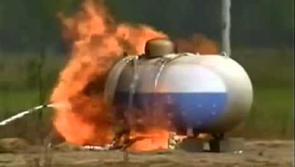
Among the most devastating of accidents likely in chemical process industry is the boiling liquid expanding vapor explosion (BLEVE). It is accompanied by highly destructive blast waves and missiles. In most situations there is also a fireball or a toxic gas cloud. Releases of toxic chemicals like chlorine and phosgene from BLEVEs have damaged large chunks of areas surrounding the BLEVE site. Propellant could reach a high pressure and temperature situation in a very short time by the use of high voltage pulsed discharge.
Once sharp depressurization occurs, BLEVE (boiling liquid expanding vapor explosion) happens immediately with a violent phase transition. A two-phase flow with high pressure and speed forms and often causes severe damage. It is also useful in other aspects such as propulsion. The numerical simulation of BLEVE for propulsion shows the pressure has a sharp increasing when phase transition begins. Then a two phase mixture flow moves forward with a high speed and compresses the gas in front.
Definition
A boiling liquid expanding vapor explosion (BLEVE) is an explosion caused by the rupture of a vessel containing a pressurized liquid that has reached temperatures above its boiling point. Because the boiling point of a liquid rises with pressure, the contents of the pressurized vessel can remain liquid so long as the vessel is intact. If the vessel’s integrity is compromised, the loss of pressure and dropping boiling point can cause the liquid to rapidly convert to gas and expand extremely rapidly.
A BLEVE is an explosion caused by a liquid which is boiling and continuing to produce a flammable vapor. If the substance is flammable, it is likely that the resulting cloud of the substance will ignite after the BLEVE has occurred, forming a fireball and possibly a fuel-air explosion.
BLEVEs, which result in very large fireballs, occur when process vessels containing flammable materials with high vapor pressures are exposed to significant external heat. A BLEVE is an explosion caused by a liquid which is boiling and continuing to produce a flammable vapor. BLEVE incidents are classified into explosions, damage (derailment), overfilling, fires, collisions, runaways, overpressure, overheating, and corrosion.
TYPES OF BLEVE
(i) Cold BLEVE
– In Cold BLEVE case, the total loss of confinement of a tank containing high pressure liquid CO2 is considered. The sudden loss of confinement of the tank leads to a violent depressurization which causes sudden expansion of CO2 because of liquid to vapor phase transition. A realistic case scenario is considered. 20440 kg of CO2 are considered in an volume of 29 m3.
The storage pressure is 57.34 bars and the temperature is the ambient (2000C). A rectangular geometry of the tank was considered. The tank position is the same with the tank position of the VCE case. Three grids of total number of active cells equal to 480,000, 780,000 and 935,000 were tested without having significant changes in the results. The results with the densest grid are presented next. The tank was discretized using 30 x 9 x 9 cells. Several domain sizes were tested. The domain size of 1290 x 250 x 20 m was chosen.
(ii) Hot BLEVE
– In Hot BLEVE case, the total loss of confinement of a tank Containing high pressure liquid propane is considered. Similar to the Cold BLEVE case, the depressurization and the sudden expansion of the propane leads to the development of high overpressures. In Hot BLEVE case, the combustion of propane assists to the further increase of the generated overpressures.
A realistic case scenario is considered. 23100 kg of propane occupies a volume of 46 m3. The storage pressure is 18 bars and the temperature is the ambient (20oC). A rectangular geometry of the tank was considered. The tank position is the same with the tank position of the Cold BLEVE cases. Three grids of total number of active cells equal to 218,000, 514,600 and 943,300 cells were tested without significant changes in the results. The results with the 514,600 cells are presented next. The tank was discretized using 18 x 6 x 11 cells. The same domain size as the Cold BLEVE case was used.
BLEVE Warning Signs
There are several warning occur container before the explosion such as the pinging sound from metal shell, discoloration of container (normally cherry red), flaking of small metal pieces, bubble or bulge on container, the steam from tank Surface, shrill sound from pressure relief valve (especially if increasing with passage of time) and the tear in tank surface .
CONDITIONS REQUIRED FOR BLEVES
For a BLEVE situation following four conditions must be present:-
1.There must be a substance in liquid form. Most of the destructive BELEV’s that have occurred have involved flammable liquids and liquefied flammable gases. BLEVE can occur with any liquid, even water. The only difference is that with nonflammable liquids there is no fireball. However, there will still be damaging effect including the propagating of creaks in the structure of the container together with possibility of subsequent failure and propulsion.
2.The liquid must be in a container like sphere, bullet, and road/rail tanker.
3.The contained liquid must be at a temperature above its normal boiling point at atmospheric pressure at the time container allows the pressure inside to build up above atmospheric pressure, the fluid, in the container is able to remain in the liquid state, even though its temperature is above its normal boiling point. This increase in pressure raises the Boiling point of the contained liquid above its boiling point.
4.There must be a failure of the container in order to have BLEVE. This container failure can be due to following courses:
•Flame impingement.
•Internal structural weakness of the container
•Failure of improperly designed SRV
•Impact from a mechanical cause such a road accident, tanker derailment allowing flammable liquid to flow out.
BLEVE MECHANISM
BLEVE mechanisms are few and often rely on very limited experimental data. Where steps of BLEVE can be summarized in the following-

a) Failure of vessel- Various causes including overload heating, external hitting or vessel corrosion may lead to a failure and sudden opening of the vessel.
b) Phase transition- When the vessel fails, an instantaneous depressurization occurs to the pressure liquefied gas stored inside. The pressurized liquid/vapor mixture initially in a saturated thermodynamic state with a temperature higher than its boiling point becomes superheated when the original vessel pressure decreases to atmospheric pressure in few milliseconds.
c) Pressurization of the Vessel-The pressurized liquid can endure with being superheated when temperature inside the vessel is well below the superheat limit temperature (SLT) of the liquid. However, if the temperature is above SLT, fast bubble nucleation will start inside and finally lead to violent splashing of liquid/vapor mixture out of the vessel into atmosphere.
d) Explosion due to depressurization and bubble nucleation- As intense phase transition in superheated state happens, the boiling of the liquid followed by bubble nucleation, the expanding vapor from both vaporization of the liquid and the initial vapor stored in the vessel will together lead to an explosion (BLEV E).
(e) Blast wave formation- With an increase in total volume of the expanding vapor, by a factor of a hundred to over a thousand fold, a powerful blast wave will form and bring damage to facilities nearby.
(f) Fireball or dispersion of toxic fluid-The blast wave and the vessel fragments will be the only effects of the explosion.

CONSEQUENCES OF BLEVE
An explosion is a gas dynamic phenomenon that, under ideal theoretical circumstances, will manifest itself as an expanding spherical heat and pressure wave front. The heat and pressure waves produce the damage characteristic of explosions. The effects of explosions can be observed in four major groups blast pressure wave effect, shrapnel effect, thermal effect, and seismic effect.
(i) Blast Pressure front Effect – The explosion of a material produces a large quantity of gases. These gases expand at a high speed and move outward from the point of origin. The gases and the displaced air moved by the gases produce a pressure front th a t is primarily responsible for the damage and injuries associated with explosions. If the BLEVE happens out in the open then the blast strength at a distance of 4 fireball radii is about 30 -40 mbar pressure . This is enough pressure to break window glass and may even be able to knock some personnel down. However if the BLEVE takes place near other objects or structures then the blast wave could cause building to collapse, or it could propel objects over considerable distances.
(ii) Shrapnel Effect – When the containers, structures, or vessels that contain or restrict the b last pressure fronts are ruptured, they are often broken into pieces that may be thrown over great distances. These pieces of debris are called shrapnel or missiles. They can cause great damage and personal injury, often far from the source of the explosion. In addition, shrapnel can often sever electric utility lines, fuel gas or other flammable fuel lines, or storage containers, thereby adding to the size and intensity of post explosion fires or causing additional explosions. Most projectiles fall short of 4 -6 fireball radii depending on the tank size, fill level, liquid temperature and position relative to the tank main axis. Severe rocket type projectiles go as far as 15 fireball radii.
(ii) Thermal Effect – Combustion explosions release quantities of energy that heat combustion gases and ambient air to high temperatures. This energy can ignite nearby combustibles or can cause bum injuries to anyone nearby. These secondary fires increase the damage and injury from the explosion and complicate the investigation process. Often, it is difficult to determine which occurred first, the fire or the explosion. All chemical explosions produce great quantities of heat. The thermal damage depends on the nature of the explosive fuel as well as the duration of the high temperatures. Detonating explosions produce extremely high temperatures of very limited duration, whereas deflagration explosions produce lower temperatures, but for much longer periods.
Fireballs and firebrands are possible thermal effects of explosions, particularly BLEVEs involving flammable vapors. Fireballs are the momentary ball of flame present during or after the explosive event. High-intensity, short-duration thermal radiation may be present with a fireball. Firebrands are hot or burning fragments propelled from the explosion. All these effects may serve to initiate fires away from the center of the explosion.
iii) Seismic Effect – As the blast pressure wave expands, and as the damaged portions of large structures are knocked to the ground, significant localized seismic or earth tremors can be transmitted through the ground. These seismic effects, usually negligible for small explosions, can produce additional damage to structures and underground utility services, pipelines, tanks, or cables.
| Consequences of a BLEVE | Maximum distance for the consequence in Meters | |||
| 60m3 tank vehicle | 110 m3 tank wagon | |||
| Collapse of building | 35 | 50 | 40 | 55 |
| Severe damage to buildings | 50 | 70 | 60 | 85 |
| 100% lethality | 90 | 150 | 110 | 190 |
| Ignition of buildings | 200 | 270 | 250 | 350 |
| 1% lethality | 220 | 310 | 310 | 410 |
| 1st degree burning, crack of window | 400 | 500 | 500 | 700 |
Table: Consequences of the heat radiation and the blast of a BLEVE of propane road or rail.
ANALYSIS OF EXPLOSION ENERGY
A BLEVE results from the sudden loss of containment of a liquid heated above its normal boiling point. The loss of containment is usually the result of a catastrophic failure of the container or vessel holding the superheated liquid. There are two contributors to the BLEVE blast wave:
(1) the compressed vapor in the container head space and (2) the vapor flashing from the superheated liquid. The magnitude of the blast also depends on the degree of superheat, that is, the temperature increment above the normal boiling point. As the degree of superheat increases, the fraction of liquid that flashes increases, thus increasing the severity of the blast. An assumption common to most of these models is that the flashing phenomenon is an adiabatic vaporization process, where the driving force for vaporization is the difference in the initial and final states of fluid enthalpy.
The question of how to calculate the explosion energy of a BLEVE has been addressed by a number of investigators. R.W. Prugh, discussed in Quantitative evaluation of ‘‘BLEVE’’ hazards that many aspects of BLEVE incidents and prescribed two methods for calculating the energy of explosion using a work method. His first method involved estimating the fraction of liquid flashed and then calculating the
isentropic work of expansion for the combined volume of the original head space vapor and the flashed vapor. The vapor was assumed to obey the ideal gas equation of state. The expansion work was equated with the explosion energy.
Prugh’s second method was an energy method. The second method equated the explosion work with the change in internal energy of the superheated liquid. This method also specifies a thermodynamic path (isentropic) for the vapor expansion. The expansion work is equated with the explosion energy. This was the method presented by the Center for Chemical Process Safety (CCPS) of the American Institute of Chemical Engineers (AIChE).
E. Planas-Cuchi, J.M. Salla, and J. Casal in “Calculating overpressure from BLEVE explosions” modified the energy method by equating the internal energy change of the superheated liquid to the irreversible work performed as the expanding vapor pushes against the surrounding atmosphere. Thus, unlike the first two methods discussed, the method of Planas-Cuchi does not result in an estimate of the maximum potential work of the explosion.
EXERGY CONCEPT
Exergy, sometimes called the thermodynamic availability, is the maximum potential work that can be performed by a system as it comes to thermal, mechanical, and chemical equilibrium with the natural environment. For a BLEVE, this means that the superheated liquid flashes from its initial state to its final state, where the final state is defined by the natural environment (ambient temperature and pressure).
D.A. Crowl demonstrated the use of the batch exergy to calculate the maximum potential work from a compressed gas or a combustible fuel. By analogy, the explosion energy for a BLEVE is given by the batch exergy, where the subscript zero denotes the final (dead) state:
E= (U—U0) + p0 (V-V0) – T0 (S-S0)
Where E is the batch exergy (kJ/kg), U is the internal energy (kJ/kg), P is the absolute pressure (N/m2), V is the specific volume (m3/kg), T is the absolute temperature (K), and S is the entropy [kJ/(K kg)].
The dead state chosen for this analysis, designated by the subscript zero, is an ambient temperature of 258C (298 K) and a pressure of one atmosphere (101.325 kPa).
EXERGY ANALYSIS OF THE BLEVE
Initially, we will consider only the thermo-mechanical energy released due to the change in states. The final state should be set at the ambient environmental conditions the fluid will be expanding into (i.e., the dead state). Choosing the initial state requires some analysis, but if no additional information is known about the system, the superheat limit temperature can be used to define the initial state. Once the initial and final states are thermodynamically defined, thermodynamic tables or software may be used with above equation to calculate the change in exergy of the system. Again, this is the maximum thermo-mechanical energy available in the system to do work.
For example, a liquid-full container of propane is assumed to BLEVE at 90% of its critical temperature, 332.9 K.
The initial pressure will then be 2103.9 kPa based on the saturation pressure at that temperature. The internal energy, entropy, and specific volume can also be obtained for a saturated liquid at the initial temperature and pressure. The propane will expand into the environment, which is at standard temperature and pressure, setting the dead state properties as superheated propane vapor at 1 bar and 258C. The maximum thermo-mechanical work, exergy, can then be calculated as follows:
E= (258.91-471.05)+101*(2.34×10-3-0.55) 298*(0.9-2.22) = 120.9Kj/kg
This value of thermo-mechanical exergy is the maximum exergy attainable for the propane system. Lesser values of exergy are possible with smaller values of superheat. The thermo-mechanical exergy is the estimate of maximum work for bringing a system from an initial state to thermal and mechanical equilibrium with its ambient surroundings.
For systems that are chemically different from the surroundings (e.g., propane vs. the natural atmosphere), an additional term appears in the expression for total exergy.
This additional term, the chemical exergy, is the work contribution that arises from bringing the system into chemical equilibrium with its environment. The chemical exergy is independent of the thermo-mechanical exergy; in other words, it is the work that can be performed by the difference in chemical potentials while the system is in thermal and mechanical equilibrium.

SAFETY MEASURES FROM BLEVE
The following are examples of safety devices that may be found on tanks to protect them from accidental fire impingement:
Pressure relief valves
Thermal barriers (i.e. thermal insulation) –
Conductive cooling
Liquid cooling
Ranking of hot BLEVE prevention measures
Pressure relief valves (PRV)
All pressure tanks in India have pressure relief valves (PRV) that open if the tank pressure exceeds some predetermined level. PRVs are designed to close again when the pressure in the tank is reduced slightly below the PRV opening pressure. This is an important point to remember — PRVs do not reduce the pressure in the tank all the way down to zero! For propane tanks PRVs are normally set at pressures between 1.7 and 2.6 MPa (250 – 380 psi).
Most tanks are not equipped with thermal barriers or water spray. Some transportation tanks such as rail tank-cars have thermal barriers. Some large stationary facilities have thermal barriers or water spray systems.
Both of these systems act to limit the heating effects of fire on the tanks and this tends to make more time available to get the situation under control. Thermal barriers and water spray systems are not perfect and tanks can still BLEVE if for some reason the water spray or thermal barrier has been damaged. However, they are much less likely to BLEVE if they are equipped with these systems.
Thermal barriers (i.e. thermal insulation)
The main cause of a hot BLEVE is heating of the steel wall at the vapor side of the tank to temperatures in excess of 550 °C. Thermal insulation around the tank can significantly retard the excessive heating of the tank wall in a fire. This will allow fire fighters enough time to reach the accident location and to cool the LPG tank to avoid the BLEVE, to extinguish the fire or to evacuate the people in the vicinity of the accident.
Conductive cooling
Additional conductive cooling of the tank wall at the vapor side of the tank by heat transfer from the tank wall to the liquid LPG can be applied to avoid heating of the tank wall above the critical temperature. This can be done by:
An alloy tissue net that is applied in the entire volume of a tank, distributing the heat evenly, avoiding overheated walls and temperature differences.
Filling the tank completely with porous alloy bulbs.
This measure is only effective if the tissue net or the alloy bulbs are in close contact with the wall and the liquid LPG in order to act as a heat conductive medium. A boundary condition is that transport vibrations, collisions, overturning or derailment does not reduce the contact area between the wall and the heat conductive bulbs or tissue nets. Sufficient additional conductive cooling in combination with a PRV will theoretically avoid a hot BLEVE.
Liquid cooling
A LPG tank wall cooling system has been patented. The idea is to use the energy from a venting PRV to drive a turbo pump spraying liquid to the inside tank top. The whole system is fitted at the inside of the LPG tank. Only the venting line will, of course, have an outside connection. In order to create a flow to drive the turbo pump and subsequent cooling of the upper tank wall in an early phase of a fire engulfment, the set point of the PRV should be a very low pressure.
TNO considers this technology to be technically feasible but not yet demonstrated in field tests. Disadvantage is that the system only works when the tank is in upright position. Furthermore it cannot be considered a proven or state-of-the-art technology. Moreover, it will be a costly solution. Also deficiencies in the spraying system will deteriorate the functionality of the system.
(For detail please refer Colin Jones, US patent, http://www.abc.net.au/ra/innovations/stories/s1253697.htm).
Ranking of hot BLEVE prevention measures
The BLEVE prevention measures have been ranked for different criteria. The table below shows the results.

BLEVE can be prevented by following ways:
By preventing the exposure of tank to fire.
By preventing mechanical damage.
By preventing over pressure of tank.
By preventing overfilling of tank.
WHAT CAN YOU DO?
•Be sure that the fixed water spray fire protection systems in plant are available and working. They provide important protection against BLEVE.
•Understand firefighting procedure to protect emergency response personnel.
•Know what the worst events that could occur in plant are, what systems are in place to ensure these systems are working properly.
•Immediately report any problems with protective safety systems and follow up to make sure they are fixed.
Author:

RAHUL SONKAR
Dip(Industrial Safety), B.Sc. (Mathematics), B.Sc.(Marine Engineering), Dip (Security Mgmt.) , Certificate Environment Study, Certificate Radiation Safety, Certificate in Comprehensive disaster Management & Climate Change, PGD (PM&IR),GI Fire ‘E’ (India), AI Fire ‘E’, MBA (Operation)